- The First Article
- The Last Article
YBQ Series Three-phase AC Variable Frequency Traction Motor is applicable to various electric vehicles (electric sedan, forklift, transportation vehicle, cruising vehicle, patrolling vehicle, traction vehicle and golf vehicle) supporting controller and supplied by accumulator and driving motor of electric vehicle.
1. Overview
1.1 Name of product: Three-phase AC Variable Frequency Motor
Product standard: Q/0303ZXP003-2013 <Variable Frequency Speed Adjustable Three-phase Asynchronous Motor for Accumulator Vehicle>
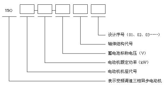
1.2 Model and specification
|
|
|
|
|
|
Example: YBQ112-7.5-72B01 means the variable frequency speed adjustable three-phase asynchronous motor for accumulator vehicle with 112 foundation code, rated power of 7.5kW, accumulator nominal voltage of 72V, shaft extension structure of 18-gear sheath (high sheath) and designed SN of 01.
1.3 Please refer to Form 1 for the code of foundation and shaft extension structure in detail.
Form 1
Foundation code |
Code of shaft extension structure |
80、90、100 |
A: 19-gear sheath; B: 18-gear sheath (high sheath); D: Optical shaft flat key |
1.4 Environmental conditions
The motor enjoys normal operation under the following environmental conditions:
a. The altitude is not above 1000m.
b. The maximum temperature of surrounding air is 40℃; the minimum temperature of surrounding air is -25℃.
c. The relative humidity is 100% and condensation is formed on the motor surface.
1.5 It is able to meet diversified working conditions such as heavy-loaded start, full-loaded climbing and high-speed operation on flat road.
1.6 Please refer to the product profile drawing and order requirements for the installation profile and technical parameters of the motor in detail.
2. Structure and working theory of motor
2.1 The motor mainly includes the stator, rotor and end cover.
2.2 The protective level of motor shell is IP 54 (please refer to GB/T4942.1 in detail).
2.3 The motor cooling model is IC410 or IC411 (please refer to GB/T1993 in detail).
2.4 S2-60min short-term working system is followed for the motor.
2.5 The insulating level of the motor is Level H.
2.6 Motor wiring
The stator winding is connected into “△” or “Y” according to the product drawing sample requirements; three guide wires are introduced and marked by U (yellow), V (green) and W (red). If the sequence of letters at the wire outlet end is same as three-phase power voltage’s phase sequence in the controller, the motor is rotated in a clockwise direction from the perspective of shaft extension end (or it is customized according to the client’s requirements).
2.7 External encoder is collocated for the motor; the pulse quantity is in accordance with the drawing sample requirements; four connective wires are introduced from the encoder; encoder connector code is DJ7041-1.5-11 (or it is collocated according to the client’s requirements).
2.8 Temperature sensor of motor
KTY84-130, temperature sensor (or it is collocated according to the client’s requirements) correspond to different resistance under different temperature; the resistance signal is transmitted to the controller for reasonable control and protection of the motor. DJ7021-1.5-11 connector (or it is collocated according to the client’s requirements) is collocated for the sensor.
3. Notice
3.1 AC variable frequency controller is collocated for the motor; the motor and controller are coordinated closely; combination can not be realized until adjustment and setup of motor parameters.
3.2 The user must strictly adhere to the operation and maintenance instruction manual to assure normal operation of the motor.
3.3 Before normal operation, 500V megameter is collocated to measure motor insulating resistance under cold status: it is above 100MΩ; under the hot status (130℃), the motor insulating resistance is not less than 0.33MΩ.
3.4 Before normal operation, the motor must be stored in a dry, clean and ventilated area; in case of long-term storage (half a year), the shaft lubricant must be inspected. The insulating resistance is not less than 20MΩ; otherwise, the motor is dried up in the drying oven for 0.5—1h; the baking temperature is between 80—100℃.
3.5 Before normal operation, the motor and speed sensor are inspected for correct, reliable and firm wiring.
3.6 The user slightly rotates the shaft extension unit and inspects the rotor for flexibility.
3.7 If the surrounding cooling air is not higher than 40℃, the stator winding (resistance method) of the motor enjoys a temperature increase limit of 105K and rolling shaft is not higher than 95℃.
3.8 S2-60min short-term working system is followed for the motor; it is forbidden to operate for a long time; work overtime is clearly specified in the ordering.
3.9 The motor receives inspection and maintenance once every half a year according to the following methods:
a. Regularly clean up mud, sand and other impurities in the shell and thus assure heat radiation of the motor.
b. Inspect the shaft for flexible rotation; clean or replace the shaft; upon cleaning, add 7015 lubricant (SH/T037017-1993) into the roller.
c. Organize well-planned maintenance at a frequency of at least once every half a year.
3.10 The motor fittings are increased in the order contract according to the client’s requirements and prices are calculated on other occasions.
3.11 The certificate of conformance and operation and maintenance instruction manual are attached to the motor.
3.12 Maintenance assurance period: The motor enjoys a maintenance assurance period of one (1) year as of the manufacturing date; the user strictly adheres to the requirements of operation and maintenance instruction manual; any fault due to improper operation is not repaired by the manufacturer; in case of any abnormality within the maintenance assurance period, the user should immediately contact with the manufacturer instead of personal settlement.
Appendix: Frequent faults and settlement methods
Symptom |
Analysis of root cause |
Settlement methods |
The motor can not be started |
1. The power supply lacks phase or power voltage is too low |
1. Inspect the stator winding for broken wire; then inspect the power voltage |
Three-phase current suffers from imbalance |
1. Three-phase power voltage suffers from imbalance |
1. Adopt the voltage meter to measure the power voltage |
Motor shaft suffers from overheat |
1. The shaft is broken |
1. Replace the shaft |
Symptom |
Analysis of root cause |
Settlement methods |
Temperature increase is too high or motor has smoke |
1. The motor suffers from overload |
1. Reduce the load or replace with a motor with rather large capacity |
Motor suffers from large vibration and abnormal sound in the normal operation |
1. The motor installation fails to meet the requirements |
1. Inspect the motor installation and make necessary adjustment |
- The First Article
- The Last Article